Gérard Deygas
🇺🇳 Niet Nederlandstalig
I open this new feed with one of my last subjects at 1/16
Declined in several versions with moderately effective improvements, the Panzer III will be qualified as a medium tank by the Wehrmacht. Widely used on the Eastern Front and in North Africa, soon exceeded it will be replaced advantageously by the Panzer IV. It will subsequently serve as an armoured escort to support the infantry rather than facing armoured forces.
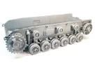
The kit: After the Stug III from the same manufacturer, I let myself be tempted by the Panzer III Ausf. J. It is no longer necessary to praise DAS Werk as much for the 1/16th as for the 1/35... The quality is there and we are never disappointed when we open the box! Based on the same chassis, we find all the ingredients faithful to the brand. Significant packaging, an impressive number of parts grouped into twenty-one plastic clusters, an illustrated assembly plan with six color profiles, a photoetched, a decal board, a translucent plastic board to restore the glasses of the episcopes, of lighthouses, two turned aluminum cannons etc... The chassis. The suspension arms in place, they will remain articulated allowing a perfect adaptation on a dio to difficult terrain!. Blank test of the undercarriage components, support rollers, rollers, pulley and sprocket...
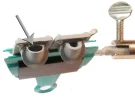
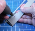
If nothing goes wrong, we’ll remove everything because these parts will be painted separately! A small remark, the molding of the supporting rollers could have been simplified thus reducing the number of parts... Indeed, the assembly of the two half parts of the rubber reveals a rather unsightly joint to fix! You should spread liquid glue on both sides to avoid using sealant. After drying, the excess glue will be removed with a half-round file; the finish will be done with fine abrasive paper. Finally, with the supporting rollers (the rollers will be treated in the same way), “break” the overly protruding rubber edge with a flat file.
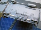
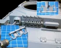
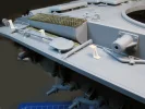
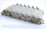
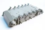
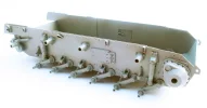
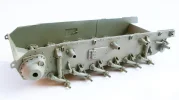
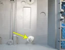
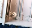
I am keeping here the same attachment as for the Stug III, a plywood board, an effective system to hold the kit during all the assembly and painting phases. For this, the frame is drilled and four nuts are glued inside, two at the front and two at the back of the body. Set the location of the holes beforehand to avoid crossing a torsion bar. In order to secure the bonding, I reinforced the nuts with Magic Sculpt. Another putty will also do the trick.
A 5 mm thick board will be screwed into the frame (6 mm screws) on it, and a wooden handle will be attached to complete this adaptation (drop of a wooden curtain rod, handle of a brush, etc.).

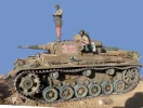
Declined in several versions with moderately effective improvements, the Panzer III will be qualified as a medium tank by the Wehrmacht. Widely used on the Eastern Front and in North Africa, soon exceeded it will be replaced advantageously by the Panzer IV. It will subsequently serve as an armoured escort to support the infantry rather than facing armoured forces.
The kit: After the Stug III from the same manufacturer, I let myself be tempted by the Panzer III Ausf. J. It is no longer necessary to praise DAS Werk as much for the 1/16th as for the 1/35... The quality is there and we are never disappointed when we open the box! Based on the same chassis, we find all the ingredients faithful to the brand. Significant packaging, an impressive number of parts grouped into twenty-one plastic clusters, an illustrated assembly plan with six color profiles, a photoetched, a decal board, a translucent plastic board to restore the glasses of the episcopes, of lighthouses, two turned aluminum cannons etc... The chassis. The suspension arms in place, they will remain articulated allowing a perfect adaptation on a dio to difficult terrain!. Blank test of the undercarriage components, support rollers, rollers, pulley and sprocket...
If nothing goes wrong, we’ll remove everything because these parts will be painted separately! A small remark, the molding of the supporting rollers could have been simplified thus reducing the number of parts... Indeed, the assembly of the two half parts of the rubber reveals a rather unsightly joint to fix! You should spread liquid glue on both sides to avoid using sealant. After drying, the excess glue will be removed with a half-round file; the finish will be done with fine abrasive paper. Finally, with the supporting rollers (the rollers will be treated in the same way), “break” the overly protruding rubber edge with a flat file.
I am keeping here the same attachment as for the Stug III, a plywood board, an effective system to hold the kit during all the assembly and painting phases. For this, the frame is drilled and four nuts are glued inside, two at the front and two at the back of the body. Set the location of the holes beforehand to avoid crossing a torsion bar. In order to secure the bonding, I reinforced the nuts with Magic Sculpt. Another putty will also do the trick.
A 5 mm thick board will be screwed into the frame (6 mm screws) on it, and a wooden handle will be attached to complete this adaptation (drop of a wooden curtain rod, handle of a brush, etc.).
Laatst bewerkt door een moderator: